Checklists, requirements and standards are commonplace in the world of Commercial and Federal Aviation. This consistency promotes occupational safety and protection of aircraft assets, resulting in fewer mishaps and increased performance for the industry. With these multitudes of requirements in place, it can be interesting to delve into those areas where clear, consolidated standards do not exist, and one such area is Aircraft Servicing Bay (Hangar) floor markings. Requirements for airfield markings are addressed in well over a dozen different standards, but they literally stop short of the hangar floor.
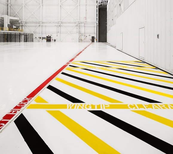
Hangar floor markings serve as visual communication of very important information, safety and restrictions. In FSB’s experience there are a wide variety of floor markings utilized, and they can vary significantly by hangar use, installation and agency/corporation. Oftentimes, when FSB is working with clients to determine the type of hangar floor markings needed the users of the facility face uncertainty and we end up providing markings similar to the previously constructed hangar. While this may be a good solution locally, the lack of consistency from installation to installation creates the potential for miscommunication and could result in injury or damage.
 In reviewing each of the standards related to airfield markings, the lack of consolidated guidance for hangar floors is a little surprising, considering the number of documents on the subject. Air Force Instruction (AFI) 32-1042 entitled “Standards for Marking Airfields” states that a future Unified Facilities Criteria (UFC 3-260-04) will be issued for airfield markings, however it is unknown if this document will address interior hangar floor markings. The “pre-decisional” version of UFC 4-211-01 (dated 22 February 2016), if implemented in its current form, will provide the most complete guidance to date. However, many of its requirements are incomplete, some appear to conflict with established safety standards, and they lack the consistency and uniformity the industry requires. To a certain degree it makes sense that once inside a hangar the airfield standards are no longer applicable. Hangar floor markings are more about a hangar’s function, aircraft type, protection, and most importantly, worker safety.
Occupational safety standards, such as OSHA and AFOSH, provide some additional insight into floor markings, but do not provide complete, clear requirements. Air Force Instruction (AFI) 91-203 entitled “Air Force Consolidated Occupational Safety Instruction” is based upon OSHA recommendations and provides the below criteria for warning colors, noting, “Safety color coding for warning signs and markers helps alert persons to the presence of hazards. Refer to Table 29.6 and 29.7 for examples of color use. Color specifications in this standard are in accordance with 29 CFR 1910.144. and 29 CFR 1910.145.”
- Black or white lettering provides contrast with basic warning and cautionary colors. Black lettering shall be used on a yellow, white or orange background. White lettering shall be used on a red, green or black background. For airfield pavement, ETL 1110-3-512 defines the color as Federal Standard 595, Colors: Black – 37038 and White – 37925.
- Green shall be the basic color for safety and first-aid equipment locations. Solid green, green and white stripes, green cross on white background, or white cross on green background can be used. Green is also used for identifying compressed gas cylinders and piping systems containing oxidizing materials. For airfield pavement, ETL 1110-3-512 defines the color as Federal Standard 595, Colors: Green – 34108.
- Orange, with the exception of fluorescent orange or orange-red used to designate biohazards, shall be used to designate electrical conduit and unguarded, dangerous parts of machines or energized equipment which may cut, crush, shock or otherwise injure, and to emphasize such hazards when equipment guards are open or removed. For airfield pavement, ETL 1110-3-512 defines the color as Federal Standard 595, Colors: Orange – 12197.
- Red shall be used to mark danger and stop. Note: Red and white are the OSHA colors for fire safety; areas with a fire extinguisher, fire alarm pull station, firefighting water or an exit typically have hangar floor markings of these colors. For airfield pavement, ETL 1110-3-512 defines the color as Federal Standard 595, Colors: Red – 31136.
- Yellow shall be used to designate caution, flammable materials and to mark physical hazards, such as strike against, stumble, trip, fall and caught-between types. For airfield pavement, ETL 1110-3-512 defines the color as Federal Standard 595, Colors: Yellow – 33538.
- Solid yellow, yellow and black stripes, and yellow and black checks may be used interchangeably for various danger areas identified in AFI 91-203, as it creates the most attention.
OSHA and ANSI both consider line widths above 2 inches to be acceptable for floor markings. AFI 91-203 also provides glimpses into the recommended line widths used in floor markings. In Chapter 7, the AFI states that aisle clear zone “… lines, two (2) to three (3) inches wide, shall be used when marking is necessary” and subsequently states, “Edges of docks shall be marked with four-inch wide yellow lines when there is a chance of workers falling.” These physical line widths are consistent with industry standard marking widths of 2, 3, 4 and 6 inches. AFI 91-203 and AFOSH Standard 91-100 both include similar language to indicate that taxi/tow lines shall be painted on hangar parking areas to aid in the safe movement of aircraft, including spots where the nose or forward wheel of the aircraft shall be positioned. If maintenance docks are utilized, each aircraft wheel location must be marked to prevent contact with the aircraft during docking. These standards also state that taxi/tow lines are not required if numerous types of aircraft use the same facility and multiple paint lines would be confusing.
In reviewing more than three dozen airfield and safety standards, many of which are referenced in the Appendix, it is clear that our industry is provided with only partial guidelines. We do not have the clear and consolidated direction on the requirements or recommendations for complete hangar floor markings, to enable us to support consistent and clear occupational safety and protection of aircraft assets. Based upon the standards in place at this time, and FSB’s experience with agencies/corporations across the United States, we propose the following standards be applied to hangar floor markings.
Hangar Floor Markings:
The following recommendations are based upon the documents referenced in the Appendix. These recommendations are heavily augmented to provide clear and consistent direction for hangar floor markings in order to support consistent and clear occupational safety and protection of aircraft assets inside the aircraft servicing bay.
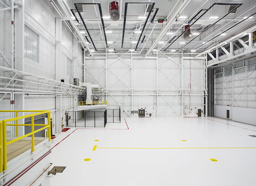
Recommendation: Hangar floors shall be reflective and light in color – this permits hangar floor markings to be clearly seen and has the added benefit of providing a clean and safe appearance, reducing lighting/energy requirements and promoting detection of Foreign Object Debris (FOD). Because hangar floor markings exist in a predominately clean, dry and lighted environment with light colored pavement and aircraft are being moved slowly by tugs, hangar floor markings do not need to be reflectorized (glass beads, etc.) nor do they require high visibility markings (adjacent or surrounding black lines). All floor markings however, shall comply with safety requirements for slip resistance.

Basis: NAVAIR 51-50AAA-2 Section 006 01 requires that where markings do not provide sufficient contrast with the surrounding pavement they shall be outlined with black, non-glossy borders. ETL 1110-3-512 does not specifically list hangars as a required location for markings to include glass beads. AFI 91-230 requires that hangar floors meet the guidance provided in ETL 96-5 (Hangar Concrete Floor Reflective Coating Criteria) which has since been superseded by UFGS 03 53 14.00 20 (Light Reflective Nonferrous Metallic Aggregate Floor System), UFGS 09 67 23.15 (Fuel Resistive Resinous Flooring, 3-Coat System) and UFGS 09 67 23.16 (Fuel Resistive Resinous Flooring, 5-Coat System). The AFI further requires floor coatings to exhibit anti-skid properties to reduce the risk of worker slips and falls and requires a minimum coefficient of friction of 0.5 for level surfaces (Chapter 7). The pre-decisional version of UFC 4-211-01 indicates that all paint for maintenance bay pavement markings comply with FS TT-P-1952.
Aircraft Tow Lines:
Recommendation: A single, continuous 6-inch wide yellow stripe should be utilized to mark aircraft tow lines extending into the hangar from apron centerlines. For large aircraft, provide a 12-inch wide by 6-foot long yellow stop line perpendicular to the tow line at the appropriate locations as determined below. For smaller aircraft, such as fighters, provide an 18-inch by 18-inch yellow square.
For hangars constructed to routinely serve a single or similar airframe in a consistent location:
Nose-In Hangars: Provide tow lines with a nose gear stop line (mark aircraft type in stop line with 6-inch black text) and optionally mark main gear stop lines.
Tail-In Hangars or combination Nose-In / Tail-In Hangars: Provide tow lines for all gear, including nose gear stop lines (mark aircraft type in stop line with 6-inch black text) and optionally mark main gear stop lines.
Note: Mark all stop locations for all wheels if utilizing maintenance docks in order to ensure proper placement and prevent adverse contact with the aircraft during docking.
For hangars constructed to routinely serve multiple aircraft in various locations:
If tow lines would become confusing, and thus potentially provide more harm than benefit, they may be omitted.
If overhead fall arrest systems are being provided in certain locations for aircraft maintenance, provide tow lines with a nose gear stop line to properly align and place the aircraft underneath.
Basis: AFI 91-203 and AFOSH Standard 91-100 both include similar language to indicate that taxi/tow lines shall be painted on hangar parking areas to aid in the safe movement of aircraft, including spots where the nose or forward wheel of the aircraft shall be positioned. If maintenance docks are utilized, each aircraft wheel location must be marked to prevent contact with the aircraft during docking. ETL 1110-3-512 Figure A-45 adds that wheel stops should be an 18-inch square yellow box. These standards also state these taxi/tow lines are not required if numerous types of aircraft use the same facility and multiple paint lines would be confusing. For consistency the taxi/tow line should match the requirement from ETL 04-2 for the apron centerline, a single, continuous 6-inch wide yellow stripe. The pre-decisional version of UFC 4-211- 01, if approved and issued, would require a single, continuous 6-inch wide yellow stripe with a 6-inch wide perpendicular yellow nose gear stop for Airforce and Navy hangars, and a 6-inch wide dark grey stripe in Army hangars.
Hangar Doors:
Recommendations: Provide 3-inch wide alternating yellow and black diagonal stripes over the area within 5 feet of all hangar door crush and pinch points, minimum. In addition, paint a minimum 14-inch by 20-inch wide “DANGER” sign outside of this clearance zone in accordance with AFI 91-203 (including Figure 29.1 and Table 29.3). Note: Crush and pinch points typically occur at door pocket sides/back and at the location in which hangar doors close/seal.
Optional Recommendations: At the hangar door’s leading edge (point of door opening), it is recommended that the above zone markings be increased to 10 feet in order to provide for the minimum hangar door opening width. For hangars constructed to routinely serve a single, or similar, airframe in a consistent location, provide a 3-inch wide yellow stripe across the hangar door threshold at the location marking 10 feet clear of the wing tip.

Basis: AFI 91-203 requires the establishment of a clear zone, i.e., five (5) feet if space allows, around all hazardous areas including crush and pinch points between structural beams and hangar doors. Hazardous areas such as crush and pinch points that cannot be eliminated by engineering controls or mechanical safeguards must be highlighted with colored paint and signs. Mark these clear zones with solid yellow or yellow and black stripes. Additionally the AFI requires approach from all sides of the hazard area to have a 14 by 20 inch or larger “DANGER” sign painted on the floor just outside the clear zone in accordance with AFI 91-203 Figure 29.1 and Table 29.3. The word “DANGER” shall be printed on top with white letters with a message below stating “HAZARDOUS AREA – STAND CLEAR DURING DOOR OPERATIONS”.
AFI 91-203 and many Airlift Wing Instructions (such as 445th AWI 21-108) require a 10-foot minimum hangar door opening width. AFI Chapter 24 indicates a hangar‘s general ventilation may be supplemented by opening hangar doors (not less than 10 feet) to provide additional air movement. Also Airlift Wing Instructions often state: “Powered hangar doors will be opened a minimum of 10 feet. A 10-foot mark will be identified on the floor, visible from the door control panel. If operational constraints require the doors to be opened less than 10 feet, the main electrical power switch for the door will be locked out (OFF) and remain locked out until the door is opened more than 10 feet or closed.”
UFC 3-260-01 Table 8-2 requires 10-foot wingtip clearance to hangar doors. AFI 91-203 Chapter 24 has multiple references to the hangar doors being opened “enough to allow complete passage of the aircraft, both in width and height, with at least 10-foot wingtip clearance on either side”, and “overhead hangar doors shall be fully opened before moving aircraft through the door entrance. Horizontal sliding doors shall be opened to permit a minimum 10-foot clearance at each wingtip.” Note: this door to wing clearance line will often conflict/overlap with the other two hangar door floor markings and is not typically an issue if the doors are always fully opened in a hangar bay prior to moving the aircraft.
Safety Corridor (Fire Lane):
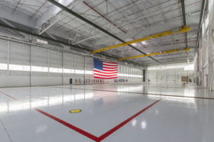
Recommendation: A continuous 6-inch wide red stripe should be utilized to mark a safety corridor around the interior perimeter of the hangar. At a minimum, the safety corridor width should be 5 feet clear; the width should be increased as necessary depending upon the size and type of equipment located along the hangar walls. Optionally 6-inch white lettering may be included within the red line to read “FIRE LANE – DO NOT BLOCK” spaced at 20 feet on center.
Basis: FAA 8083-30, Safety, Ground Operations and Servicing (Chapter 11) recommends safety lanes, pedestrian walkways and fire lanes should be painted around the perimeter inside the hangars as a safety measure to prevent accidents and keep pedestrian traffic out of work areas. UFC 3-260-01, Airfield and Heliport Planning and Design indicate a 5-foot wide safety corridor (fire lane) should be included around the perimeter inside hangars.
The pre-decisional version of UFC 4-211-01, if approved and issued, indicates a continuous 6-inch wide yellow boundary line (Airforce) and a 5-foot wide solid yellow safety corridor (Army and Navy). The Navy has an additional requirement that in areas with vehicular traffic the safety corridor (lane) be denoted with a 6-inch wide yellow border and 6-inch wide diagonal yellow stripes. Yellow safety corridors would represent a change from the previous common practice of utilizing a continuous 6-inch wide red line around the interior perimeter of hangars, and it presents a potential conflict with the current requirements for marking the hangar door hazards indicated above. For this reason, FSB’s recommendation for the safety corridor won’t be changed until the new UFC is issued.
Fire Extinguishers and Fire Alarm Manual Pull Stations:

Recommendation: Provide a solid red painted area at the floor in the vicinity of fire extinguishers, fire alarm manual pull stations, etc. Painted area shall be a minimum of 48 inches wide by 48 inches deep.
Basis: The pre-decisional version of UFC 4-211-01, if approved and issued, would require a red perimeter box with a 2-foot clearance around these types of items. The 2-foot clearance in all directions would result in a minimum 4-foot area.
Emergency Eye Wash / Shower and First Aid:
Recommendation: Provide a solid green painted area at the floor in the vicinity of emergency eyewashes, showers and first aid kits. Painted area shall comply with safety requirements for slip resistance suitable for a potentially wet environment and be of sufficient size to maintain clearance and access, at a minimum, 24 inches in all directions from the fixture (minimum 48 inches wide by 48 inches deep).
Basis: AFI 91-203 requires emergency eyewashes within a 100-foot travel distance and states that permanently- installed units and self-contained units installed in fixed locations shall be identified with a highly visible sign. The area around or behind the unit, or both, may be painted with green and white stripes if needed to increase visibility for easy identification by the user. AFI 91-203 also states that green shall be the basic color for safety and first-aid equipment locations. Solid green, green and white stripes, green cross on white background, or white cross on green background can be used. The pre-decisional version of UFC
4-211-01, if approved and issued, would require a green perimeter box with a 2-foot clearance around these types of items. The 2-foot clearance in all directions would result in a minimum 4-foot area.
Aircraft Jack Points:
Recommendation: Provide a continuous 3-inch wide black stripe at the boundary of the acceptable aircraft jacking points, when conditions and structural analysis require such limitations. Just inside this area, provide 2-inch tall black text stating, “AIRCRAFT JACK PLACEMENT”.
Basis: Depending upon the size and weight of the aircraft, soil conditions and pavement design, locations for acceptable jack points may be limited to certain areas specifically engineered to support jacking loads. When applicable, and limited, the boundary of these allowable jacking points shall be marked.
Aircraft Static Ground Points:
Recommendation: Provide an 18-inch diameter yellow circle around all aircraft static ground points, leaving the center ground receptacle unpainted. Provide a 2-inch wide red border around the yellow circle (outside diameter of 22 inches). In the yellow area of the mark, paint the word “GROUND” in 1-inch tall black text, and the date stated in ½-inch tall black text.
Basis: ETL 1110-3-512 (Figure A-44) requires static ground points to be an 18-inch diameter yellow circle with a 6-inch wide black border. Other grounding standards require static ground points to be an 18-inch diameter yellow circle with a 2-inch wide black border with black text for date and ohm rating.
UFC 3-575-01 (Figure 2-3) requires static ground points to be 18-inch diameter yellow circle with a 2-inch wide red border and black text. The pre-decisional version of UFC 4-211-01 will reference UFC 3- 575-01 Figure 2-3 for Army, Air Force and Navy hangars when approved and issued.
Electrical Panels, 400Hz Gateboxes, etc.:
Recommendation: Provide 3-inch wide alternating black and white diagonal stripes over the area required for clearance and access.
Basis: To ensure that an electrical panel can be accessed at all times for inspection, maintenance or emergency, OSHA requires the working space in front of the equipment must be at least 30 inches wide (or the width of the equipment) and have at least 6.5 feet of vertical clearance. A clearance of at least 3 feet is required for equipment using 120 to 250 volts. The workspace also must permit at least a 90-degree opening of all hinged panels and equipment doors. This workspace space cannot be used for permanent fixtures or temporary storage.
Door Swings:
Recommendation: Provide 3-inch wide alternating black and white diagonal stripes over the area required for clearance and access to doors.
Basis: FSB extensive hangar design experience.
Edges of work docks, pits, etc.:
Recommendation: Provide a continuous 4-inch wide yellow stripe at all edges of work docks, pits, etc. where there is a trip or fall danger.
Basis: AFI 91-203 Chapter 7 requires that dock surfaces be smooth and even. Where necessary, aisleways shall be marked. Edges of docks shall be marked with 4-inch wide yellow lines when there is a chance of workers falling.
Low clearances overhead:
Recommendation: Provide 3-inch wide alternating yellow and black diagonal stripes over all floor areas in which there is not at least 7 feet of vertical clearance.
Basis: AFI 91-203 Chapter 7 requires whenever there is less than seven (7) feet of headroom over stairs, obstructions shall be padded. When they cannot be padded, obstructions shall be color-coded yellow or yellow-and-black stripes to highlight the hazards. In all cases, caution signs shall be used to warn people of low clearances.
Machinery, Equipment:
Recommendation: Provide 3-inch wide alternating yellow and black diagonal stripes over the floor area determined to be a hazard potential near fixed machinery and equipment.
Basis: AFI 91-203 states that marking of machine clear zones is optional. The installation’s safety office and shop supervisor shall determine the need to mark clear zones based upon hazard potential. Yellow or yellow and black hash-marked lines, two (2) to three (3) inches wide, shall be used when marking is necessary.
Storage Areas:

Recommendation: Provide a continuous 3-inch wide black stripe at the boundary of the acceptable storage area(s). Just inside this area, provide 2-inch tall black text stating, “STORAGE AREA: 12 FOOT MAXIMUM HEIGHT, AIRCRAFT NOT PERMITTED”.
Basis: If storage areas are to be utilized in an aircraft servicing bay they must be considered in the fire protection strategy – including layout and location of HEF, AFFF, underwing nozzles and triple IR flame detectors. Additionally, these storage areas will no longer be appropriate locations for aircraft. Height of storage shall be kept below 12 feet for Class I through Class IV commodities.
Obstructions:
Recommendation: Mark obstructions, such as utility stands in the hangar bay, with a continuous 3-inch wide orange stripe 2 feet clear of the obstruction.
Basis: The pre-decisional version of UFC 4-211-01, if approved and issued, would require an orange perimeter box with a 2-foot clearance around these types of items.
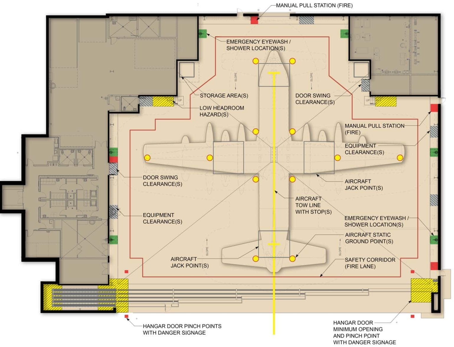
Example Hangar Floor Marking Plan:
The example hangar floor marking plan, on the following page, is a graphic representation of the above recommendations as may be implemented in an aircraft hangar.
Appendix A: Example Hangar Floor Marking Plan:
Appendix B: List of Related Airfield and Safety Standards:
UFC 3-260-01, Airfield and Heliport Planning and Design, 17 November 2008
For Pavement Marking, UFC 3-260-01 states it is not the applicable document and directs to the following standards:
Air Force AFI 32-1042, Standards For Marking Airfields (UFC 3-260-04)
ETL 04-2, Standard Airfield Pavement Marking Schemes (UFC 3-260-04)
Army TM 5-823-4, Marking of Army Airfield-Heliport Facilities (UFC 3-260-04)
Navy/Marines NAVAIR 51-50AAA-2
FAA AC 150/5340-1, Marking of Paved Areas on Airports
UFC 3-260-04 (not yet released) Note: It is unknown if this document will address interior hangar markings. AFI 32-1042, Standards for Marking Airfields, 14 January 2015
ETL 04-2, Standard Airfield Pavement Marking Schemes, 19 July 2004
UFC 3-260-02, Pavement Design for Airfields, 30 June 2001
UFC 3-260-05A, Marking of Army Airfield Heliport Operational and Maintenance Facilities, 16 January 2004 UFC 3-575-01, Lightning and Static Electricity Protection Systems, 1 July 2012
UFC 4-211-01N, Aircraft Maintenance Hangars: Type I, Type II and Type III, 16 December 2009
UFC 4-211-01N ITG for Maintenance Hangar Design and Planning Guidance for F35, 12 January 2010 UFC 4-211-01 Design Guide for Air Force Fighter Hangar/AMU Facility, 1 August 2015
UFC 4-211-01, Pre-Decisional Aircraft Maintenance Hangars, 22 February 2016
NAVAIR 51-50AAA-2 (Commander, Naval Air Systems Command), General Requirements for Shorebased Airfield Marking and Lighting, 1 June 2006
FAA Advisory Circular 150/5340-1, Standards for Airport Markings, 27 September 2013
TT-P-1952, Federal Specification for Paint, Traffic and Airfield Marking, Waterborne, 17 February 2015
ETL 1110-3-512, Army Airfield and Heliport Markings, 30 September 2015
ETL 97-18, Guide Specification for Airfield and Roadway Marking, 5 December 1997
AFJMAN 32-1015, Airfield, Heliport and Roadway Marking Note: This document will replace AFI 32-1042 per the 1997 version of ETL 97-18 – however this does not appear accurate, as AFI 32-1042 has been updated as recently as 2015.
AFMAN 32-1076, Design Standards for Visual Air Navigation Facilities, 1 December 1997
AFI 32-1065, Grounding Systems, 12 January 2015
AFI 21-101, Aircraft and Equipment Maintenance Management, 14 April 2008
AFI 21-101 ANG Supplement to Aircraft and Equipment Maintenance Management, 12 November 2009 445th Airlift Wing Instruction, 31 August 2011 (and similar orders)
AFI 91-203, Air Force Consolidated Occupational Safety Instruction, 17 September 2015
AFOSH STD 91-100, Air Force Occupational Safety and Health Standard, 1 May 1998
AFOSH STD 91-100, ANG Supplement to Air Force Occupational Safety and Health Standard, 28 Oct 2010 AFOSH STD 91-501, Air Force Consolidated Occupational Safety Standard
AFOSH STD 91-66, General Industrial Operations
FAA 8083-30, Safety, Ground Operations and Servicing (Chapter 11)
NFPA Standard 409, Aircraft Hangars
OSHA Standards 1910.22 https://www.osha.gov/pls/oshaweb/owadisp.show_document?p_table=STANDARDS&p_id=9714
OSHA Standards 1910.144 https://www.osha.gov/pls/oshaweb/owadisp.show_document?p_table=STANDARDS&p_id=9793
Superseded Documents (Referenced in Above Criteria):
TM 5-823-4 (superseded by TM5-923-4), TM 5-923-4 (superseded by UFC 3-260-05A), ETL 94-1 (superseded by ETL 04-2), ETL 96-5 (superseded by UFGS 03 53 14.00 20, UFGS 09 67 23.15 and UFGS 09 67 23.16),
AFR 88-16 (superseded by current ETL 04-2)
Interested in learning more, contact Laure Majors at busdev@fsb-ae.com or call her direct at 405.840.2931.


 YWCA CEO Jan Peery, said Oklahoma currently ranks sixth in the nation for women killed by men and that, in domestic violence situations, shelters are the closest thing a community has to homicide prevention. The Thelma Gaylord emergency shelter is the only certified women’s shelter in the county and serves about one fourth of the state’s total population.

 The FSB Design Discovery Lab allows owners to: